Archived board. This is a read-only archive of the Fast Tracks forums, active 2004–2016. Posting closed in May 2016; the board was preserved as a static site in 2026. Some images were lost before archiving and are marked where they appeared.

Fast Tracks

Model Railroading Discussion Forums

Return To The Fast Tracks Website

The Fast Tracks discussion forums have been closed. Click Here for more information.

It is currently Thu Aug 06, 2026 12:00 am

All times are UTC - 5 hours [ DST ]


Forum locked This topic is locked, you cannot edit posts or make further replies.  [ 5 posts ] 
Author Message
 Post subject: Railbender
PostPosted: Tue Aug 02, 2005 4:32 pm 
Offline

Joined: Tue Aug 02, 2005 7:34 am
Posts: 21
OK, from looking at the "Mini-jig" that you are releasing soon, it would seem the only part of the turnout that would still need to be made is the stock rails (unless you use hinges for the point rails, but I plan on not using hinges, and want it one solid piece from the frog to the points.

Now the question becomes, how accurate is the scale? I don't mean to imply that is inacurate. I am wondering to how many thousandths of an inch is the scale. Since I would be bending the rail to HO Scale, Standard Guage, tolerances have to be pretty tight. I've read the instruction sheet and I could not find (unless I missed it somewhere, which is VERY possible) information on what the scale on the dial is so I can make say pieces for 36" track radius for a curved turnout.

Thanks again!

Ken L.


Top
 Profile  
 
 Post subject:
PostPosted: Wed Aug 03, 2005 10:16 pm 
Offline
Site Admin

Joined: Fri May 07, 2004 11:22 pm
Posts: 311
Location: Port Dover, Ontario
(!empty($user->lang['QUOTE'])) ? $user->lang['QUOTE'] : ucwords(strtolower(str_replace('_', ' ', 'QUOTE'))):
Now the question becomes, how accurate is the scale?


Hi Ken,

Actually, the scale is not calibrated at all. Its use is to simply allow you to get a close replication of a radius when needed.

When building a curved turnout, or curved track, what is most critical, is that the rail is "pre-stressed" to a curve. I find that I make about three different sizes of radii, small, medium and large, depending on the application.

As long as the rail is *closely* bent to the size needed, the spikes, or PC board ties will keep it in place. If the rail is not pre-bent, we have found that the stresses in the straight length of rail will be enough to break the solder joints over time, as it will constantly be trying to straighten itself out. Pre-stressing the rail to a radius will eliminate this problem.

With the spiked trackwork, pre-stressing the rail to a radius will make constructing the turnout much easier as you will not be constantly fighting the rail. When using the "Frog Helper", you can pre-bend the rail and insert it into the tool, where it will be held straight while soldering. Once removed, it will return to a piece of rail with stresses in a curve, making the placement of the curved frog much easier.

Hope this helps.

_________________
Cheers!

Tim Warris
Fast Tracks
http://www.fast-tracks.net
service@fast-tracks.net


Top
 Profile  
 
PostPosted: Thu Aug 04, 2005 12:31 am 
Offline

Joined: Tue Aug 02, 2005 7:34 am
Posts: 21
I just had an idea, and wanted to ask could it work.

I would be using the regular #8 Turnout Assembly Jig to make a curved #8 Turnout, and here's how. Please let me know what you think.

It would be made in sub Assemblies

First Sub Assembly: Outside Stockrail

Solder Prestressed piece of rail to 1st, 4th, 7th and 10th Tie (counting from "Top" of Jig to bottom as shown in photos)

Second Sub Assembly: Inside Stock Rail

Solder Prestressed piece of rail to 2nd, 5th, 8th, and 9th Ties

Third Sub Assembly: Frog/Points Assembly (No Hinges):

Solder Prestressed pieces of rail to form Frog and points. Solder to 3rd and 6th tie (6th tie only to one of two point rails)

Secure Outside Stockrail Sub Assembly to proper outside radius curve.

Using Track Gauge, Solder Inside Stock Rail to 10th tie.

Secure remaining part of Inside Stock Rail Sub Assembly to proper Inside radius Curve

Take Frog/Points assembly, and using Track Gauge, secure assembly and solder ties to both inside and outside stock rails.

This way, the jig can be used to solder the rails to the ties, and although a bit complicated, get a curved turnout without having to completely "handlay" the non-frog part of the turnout. Would such an idea work in your estimation? Thanks.

Ken L.


Top
 Profile  
 
PostPosted: Thu Aug 04, 2005 8:23 am 
Offline

Joined: Tue Aug 02, 2005 7:34 am
Posts: 21
The only issue I am comming up with is determining the inside Radius for the curved turnout. I remember reading somewhere in this forum about the issues of the manufactured curved turnouts and the "fudge factor" they use to make their "stated" radii. I'm trying to figure out, is there a way to calculate what a 7 degrees 9 minutes angle change a 36" outside radius into. The prototype uses degrees to calculate the radius of their curves somehow (I still don't understand that myself how that works!) but shouldn't there be a way to calculate what the inside radius for a curved turnout should be with knowing the Frog Angle. I'm not a drawing engineer so I do not know how to calculate, let alone draw such things, and geometry is the one math area I am terrible in. Algebra is easy for me, but I can't handle geometry :-(

Thanks all!

Ken L.


Top
 Profile  
 
PostPosted: Sat Aug 20, 2005 2:07 am 
[quote="kleaverjr"]... The prototype uses degrees to calculate the radius of their curves somehow (I still don't understand that myself how that works!) ...

Ken, et al,

Actually, "radius" is mostly a modelling thing. Most twelve-inch-to-the-foot railroads aren't drawn up using turn radii because (a) the radius changes as the track eases into the turn (easements) and (b) the "center" of the hypothetical circle would be too far away, and probably too inaccessible to do any kind of arc scribing. Imagine trying to pound a stake into solid rock 1000 feet into a mountain to get that 1000 foot radius turn in a narrow gorge. ;-)

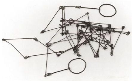
What really happened was that surveyors would measure curves in "degrees per chain." A chain is a surveyor's tool -- quite literally a chain 66 feet long (ever wonder why an acre is the size it is? 2 chains x 5 chains = 1 acre) and the surveyor would have his assistant pull the chain tight to 66 feet "straight ahead." Looking through his transit (a small scope with a compass beneath it,) he would then have the assistant go a set number of degrees to the left or right of the point and drive a stake. Curves along the Right of Way might start out at some fraction of degree per chain, and get progressively tighter, say to two or three degrees per chain, and then ease back out to straight on the other end of the turn. The advantage here is that if you knew you had to make 30 degrees of turn, you could spread that out over a certain number of chains without needing much more than the transit and chain.


Attachments:
Surveyor'sChain.jpg
Surveyor'sChain.jpg [ 27.55 KiB | Viewed 8020 times ]
Top
  
 
Display posts from previous:  Sort by  
Forum locked This topic is locked, you cannot edit posts or make further replies.  [ 5 posts ] 

All times are UTC - 5 hours [ DST ]


Who is online

Users browsing this forum: No registered users and 1 guest


You cannot post new topics in this forum
You cannot reply to topics in this forum
You cannot edit your posts in this forum
You cannot delete your posts in this forum
You cannot post attachments in this forum

Search for:
cron
Powered by phpBB® Forum Software © phpBB Group