Archived board. This is a read-only archive of the Fast Tracks forums, active 2004–2016. Posting closed in May 2016; the board was preserved as a static site in 2026. Some images were lost before archiving and are marked where they appeared.

Fast Tracks

Model Railroading Discussion Forums

Return To The Fast Tracks Website

The Fast Tracks discussion forums have been closed. Click Here for more information.

It is currently Thu Aug 06, 2026 12:00 am

All times are UTC - 5 hours [ DST ]


Forum locked This topic is locked, you cannot edit posts or make further replies.  [ 6 posts ] 
Author Message
 Post subject: Combination crossing
PostPosted: Sun Jan 01, 2006 11:50 am 
Offline

Joined: Mon Nov 14, 2005 8:50 pm
Posts: 73
Location: Cassville, MO
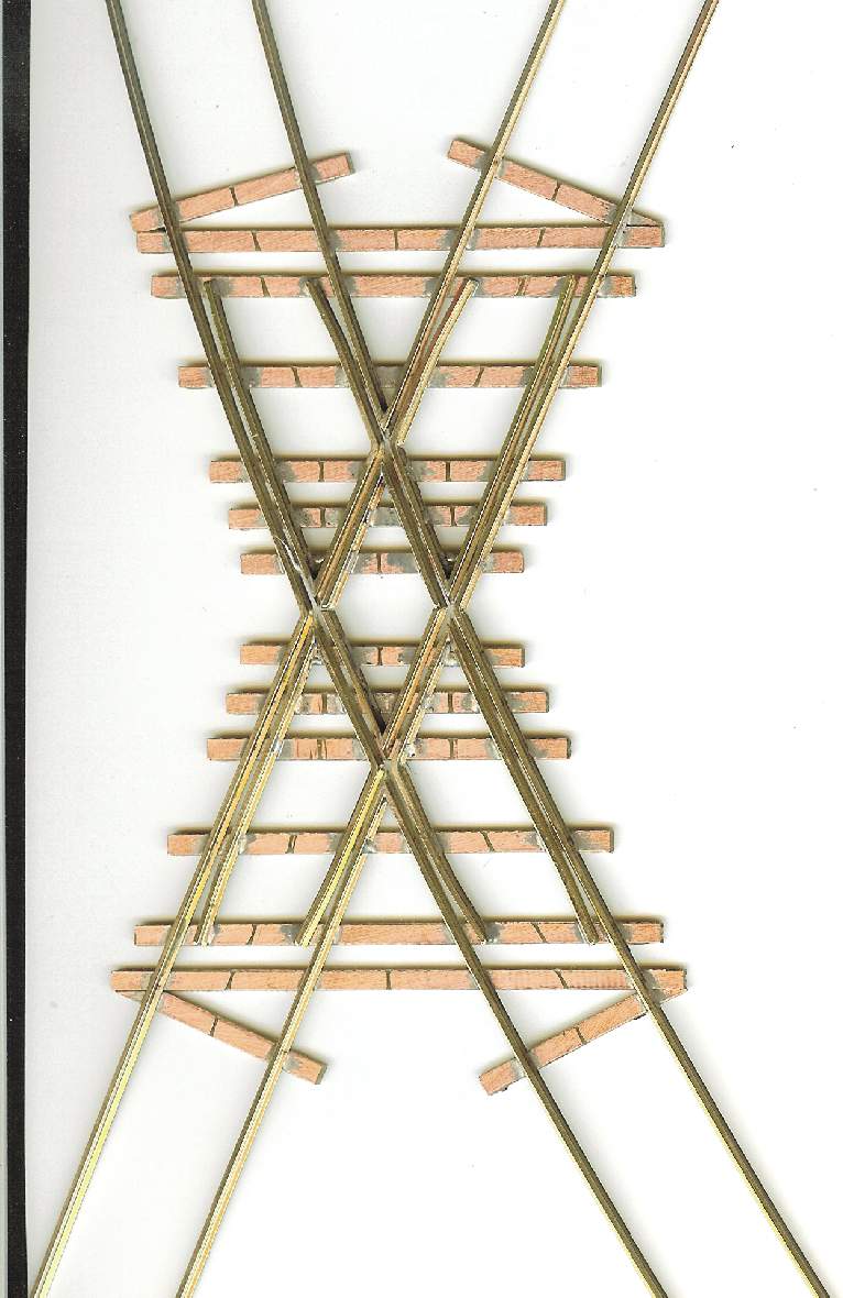
Here is a scan of an HO scale 20" radius crossing a straight track at 30 degrees. I used a printed template designed in Corel Draw, attached the PCB ties to it, then formed and soldered the rails to the PCB ties. Without the experience gained using Fast Tracks fixtures and tools I probably would never have attempted it. It was not that difficult to do, about 3 hours for the first one. Subsequent ones should take no more than a couple of hours. Not bad when you only need one or two of a kind. Frogs were ground on a small universal fixture I fabricated.


Attachments:
File comment: HO 20" radius crossing straight tracks @ 30 deg
2 curved straight crossing 20R 30 deg.jpg
2 curved straight crossing 20R 30 deg.jpg [ 96.37 KiB | Viewed 11383 times ]
Top
 Profile  
 
 Post subject:
PostPosted: Sun Jan 01, 2006 7:49 pm 
Offline

Joined: Mon May 24, 2004 6:02 pm
Posts: 63
Location: vestal, ny
littletree,
looks very nice!!
how is it operationally?


Top
 Profile  
 
 Post subject:
PostPosted: Sun Jan 01, 2006 11:44 pm 
Offline

Joined: Mon Nov 14, 2005 8:50 pm
Posts: 73
Location: Cassville, MO
Don't know yet how it will do inserted into powered trackwork but wheelsets flow thru it smoothly. I will be a while before I can try it otherwise.


Top
 Profile  
 
 Post subject: Re: Combination crossing
PostPosted: Mon Jan 02, 2006 2:23 pm 
Offline

Joined: Mon Nov 21, 2005 9:28 pm
Posts: 44
littletree (!empty($user->lang['WROTE'])) ? $user->lang['WROTE'] : ucwords(strtolower(str_replace('_', ' ', 'WROTE'))):
It was not that difficult to do, about 3 hours for the first one..

I made one crossing and had some difficulty getting the butt-join of the two halves at the center aligned correctly. I notice you have no tie at that point. I soldered one half to half the width of a tie and then soldered the other half to the same tie. I'm curious why you dd it the way you did? I felt that the tie gave me support under the joint as I soldered it, helping keep the whole thing flat. All I had to worry about was keeping everything aligned as I soldered it. I feel that a tool (just a couple of strips of steel or aluminum the width of the space between the guard rail and the stock rail) could have been very helpful at that point. Putting them into the flangeways across the joints as I soldered them would have locked the two halves together in registration. Mine came out well and things run through it smoothly, but it was very tough getting all of them lined up at once.

Jim


Top
 Profile  
 
 Post subject:
PostPosted: Mon Jan 02, 2006 5:41 pm 
Offline

Joined: Mon Nov 14, 2005 8:50 pm
Posts: 73
Location: Cassville, MO
I soldered the frog points of the diamond before they were placed into the crossing. They were the last items to go in during assembly. Each half was fine tuned to fit by filing a little at a time and comparing it to my template. I always print two copies of the template, one to attach the ties to and one for checking parts during frog tip soldering before soldering them to the ties. There is a very small gap where the two frog halves meet. It doesn't present any problems. I use pieces of aluminum to help keep the flangeway clearance so solder won't stick to it. As for not putting a tie in the center, I felt it would be better to have a full height wood tie there for support. Don't really know it there is a difference. I may try a PCB tie there on others. This may help on rail support in other ways, especially on the solidity of soldering them at this place.


Top
 Profile  
 
 Post subject:
PostPosted: Mon Jan 02, 2006 8:39 pm 
littletree (!empty($user->lang['WROTE'])) ? $user->lang['WROTE'] : ucwords(strtolower(str_replace('_', ' ', 'WROTE'))):
This may help on rail support in other ways, especially on the solidity of soldering them at this place.

That's exactly where I was going with the question. I've found that you sometimes have to put some pressure on the trackwork as you join it up to the layout and I sure didn't want to hear a "plink"! I managed to get it installed ok and it's never derailed anything, so I guess I got it right. I tested it by backing a consist of underweigt passenger cars through it at about (HO scale) 50mph. If it behaves there, I'd say it's ok.

You used exactly what I was thinking of with the aluminum pieces to get stuff lined up. I've got to find some stock that's about right and make a couple. Thanks for the answer.

Jim


Top
  
 
Display posts from previous:  Sort by  
Forum locked This topic is locked, you cannot edit posts or make further replies.  [ 6 posts ] 

All times are UTC - 5 hours [ DST ]


Who is online

Users browsing this forum: No registered users and 1 guest


You cannot post new topics in this forum
You cannot reply to topics in this forum
You cannot edit your posts in this forum
You cannot delete your posts in this forum
You cannot post attachments in this forum

Search for:
cron
Powered by phpBB® Forum Software © phpBB Group