Archived board. This is a read-only archive of the Fast Tracks forums, active 2004–2016. Posting closed in May 2016; the board was preserved as a static site in 2026. Some images were lost before archiving and are marked where they appeared.

Fast Tracks

Model Railroading Discussion Forums

Return To The Fast Tracks Website

The Fast Tracks discussion forums have been closed. Click Here for more information.

It is currently Thu Aug 06, 2026 12:00 am

All times are UTC - 5 hours [ DST ]


Forum locked This topic is locked, you cannot edit posts or make further replies.  [ 3 posts ] 
Author Message
 Post subject: Turnout measurements
PostPosted: Thu Jun 07, 2007 6:35 pm 
Offline

Joined: Thu Jun 07, 2007 6:23 pm
Posts: 3
Location: Gothenburg, Sweden
Hello!

In order to use xtrkcad for layout planning I need to tell the program some info about the different design elements. The NMRA turnouts are already in a library, but the Y, threeway and crossover I have to define myself. Is there any tables where I can find the measurements. I'm interested in N-scale.

Thanks in advance
Nils-Olov


Top
 Profile  
 
 Post subject:
PostPosted: Fri Jun 08, 2007 5:51 am 
I will explain myself a little better. there are some measurements on the different pages that describe the turnouts. but all the figures I need aren't there.
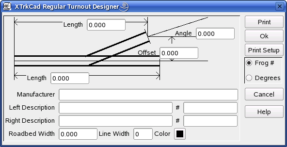
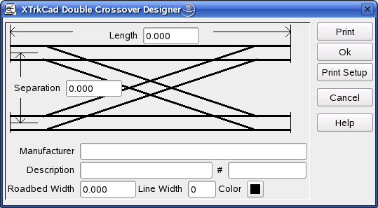
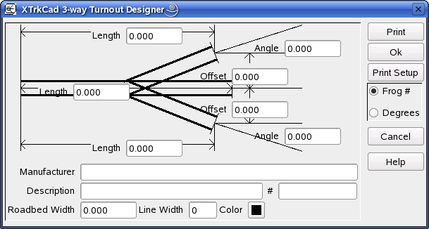
I attach a couple of figures that explains what I need. I suppose that the best measures are the minimum lengths and the offset that corresponds to that length.
The center distance for the N scale double crossovers seems to be wrong.
When i have all information I need I intend to post the library on this site and on the xtrkcad site if there are no objections

Regards
Nils-olov


Attachments:
File comment: Regular turnout
regular_turnout.png
regular_turnout.png [ 23.75 KiB | Viewed 6973 times ]
File comment: Double crossover
double_crossover.png
double_crossover.png [ 19.72 KiB | Viewed 6973 times ]
File comment: 3-way turnout
3-way_turnout.png
3-way_turnout.png [ 26.08 KiB | Viewed 6973 times ]
Top
  
 
 Post subject:
PostPosted: Fri Jun 08, 2007 11:06 am 
Offline
User avatar

Joined: Sat Aug 13, 2005 10:48 am
Posts: 365
Location: East Texas - USA
Just a suggestion:
1. Print out the N scale templates.
2. Carefully measure the length distances and the offsets. (Pick point on the templates that are easy to measure up as close as possible).
3. Measure the length from the offset point to the intersecting point. Compute the angle ratio.
4. Use formula below to get a very close approximation of the actual angle:
Angle in decimal degrees is = 2*DEGREES(ATAN(0.5/(<angle ratio>)))

(Use a spreadsheet to get the formula to work).
(e.g., for 1:6 angle=2*(DEGREES(ATAN(0.5/(6))) = 9.52728338).

5. Enter the data and examine the results ? tweak as necessary.

UPDATED - just noticed the software allows simple frog number (the angle ratio) to be directly entered - so you've got it real easy with some careful measurements. Still check and tweak.

_________________
-ed mccamey-
COSLAR RR - http://www.coslar.us/
NMRA Standards and Conformance Department
PROTO & FINE Scale Coordinator
I estimate I have about 5 pounds of coupler springs somewhere in the vicinity of my workbench.


Top
 Profile  
 
Display posts from previous:  Sort by  
Forum locked This topic is locked, you cannot edit posts or make further replies.  [ 3 posts ] 

All times are UTC - 5 hours [ DST ]


Who is online

Users browsing this forum: No registered users and 1 guest


You cannot post new topics in this forum
You cannot reply to topics in this forum
You cannot edit your posts in this forum
You cannot delete your posts in this forum
You cannot post attachments in this forum

Search for:
cron
Powered by phpBB® Forum Software © phpBB Group