Archived board. This is a read-only archive of the Fast Tracks forums, active 2004–2016. Posting closed in May 2016; the board was preserved as a static site in 2026. Some images were lost before archiving and are marked where they appeared.

Fast Tracks

Model Railroading Discussion Forums

Return To The Fast Tracks Website

The Fast Tracks discussion forums have been closed. Click Here for more information.

It is currently Thu Aug 06, 2026 12:00 am

All times are UTC - 5 hours [ DST ]


Forum locked This topic is locked, you cannot edit posts or make further replies.  [ 3 posts ] 
Author Message
 Post subject: 3way, no hinge
PostPosted: Sun Dec 30, 2007 6:00 pm 
Offline

Joined: Wed Dec 05, 2007 12:45 pm
Posts: 16
Hi all,

I've just finished my second 3way (On30 C83) and it works much better than my first attempt, however, I'm still not sure to "hinge or not to hinge."

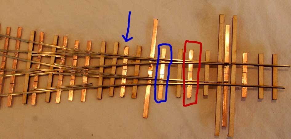
As you can see in the attached photo, I did NOT solder the first set of points to the first PCB tie to the left of the throwbar (the one circled in red). This is the place the instruction say to solder it and I did so on my first 3-way. Even with the hinge this was *very* stiff. By adding an additional PCB tie (circled in blue), I was able to solder the switch points to it and they move freely.

The second set of points are supposed to be attached (per instructions) where the blue arrow is. Instead, I soldered them to the next PCB tie to the left. These points move, but are a little stiff.

So two questions, (1) Is there a reason that the points can't be fixed further back like this thus eliminating the need for a hinge or should a hinge be installed anyway? (2) How "stiff" is too stiff for throwbar? I plan on switching these by hand either with a Caboose industries ground throw or perhaps contact switches. They are definitely tighter than my regular turnouts, but do move. I'm trying to figure this out before I put the trackage down and then learn that the points are too stiff for regular movement.

TIA
Robert


Attachments:
3wayhinge.jpg
3wayhinge.jpg [ 40.75 KiB | Viewed 6843 times ]
Top
 Profile  
 
 Post subject:
PostPosted: Sun Dec 30, 2007 6:50 pm 
Offline
User avatar

Joined: Sat Aug 13, 2005 10:48 am
Posts: 365
Location: East Texas - USA
Robert,

Nice work. The idea behind the hinging points is to ascertain the gage line and not have the longer moving points cause a squeeze of the gage. If you are able to maintain gage through the 3-point with the longer throw, then all is well. Check the point spread on the inside points - this may be too wide and cause through problems on the straight and right diverging.

Too 'strong' a throw will give stress to the points where the rails are soldered to the PC tie bars. This CAN lead to a stress fractured joint requiring repairs. Not always the case - but certainly has happened to many (myself included) over time. Generally only longer throw with smaller rails are fully safe - not really an option with a 3-way, though building with code 70 or even code 55 rails would help.

Hinging just the PC tie and switch blade points would help a lot - but is a more time consuming and requires some practice to construct. Otherwise, only testing with your manual throws (set up one installation) and seeing just what problems arise. Remember though the stress will be more likely to only show a failure latter over time - when all the installations are complete.

_________________
-ed mccamey-
COSLAR RR - http://www.coslar.us/
NMRA Standards and Conformance Department
PROTO & FINE Scale Coordinator
I estimate I have about 5 pounds of coupler springs somewhere in the vicinity of my workbench.


Top
 Profile  
 
 Post subject:
PostPosted: Sun Dec 30, 2007 7:30 pm 
Offline
User avatar

Joined: Sat Aug 13, 2005 10:48 am
Posts: 365
Location: East Texas - USA
Robert,

You may want to experiment with a 'partial' hinged heal and fully hinged point. The following are pictures of a yet uncompleted turnout.

First - I'm using code 75 leadalloy steel rail. This rail is softer than nickel silver.

Second - the stock rails are not notched - I file the point blade for a prototypical fit.

The heal 'hinge' is the rail head and base cut leaving only the rail web inside as the hinging point. This gives a very thin, but still strong rail connection - allows electrical continuity and flex bends very nicely. The flex is so modest, I've never had troubles with this breaking.

📷 Image no longer available
Originally hosted at www.coslar.us — the host went away before this archive was made.
📷 Image no longer available
Originally hosted at www.coslar.us — the host went away before this archive was made.


The point attachment to the tie bar follows Tim's double slip practice and recommendation. Removed the copper cladding. I used a 0.020" brass rod and bent it at a 90 degree to form a spike head. Then filed and fitted the top angled head for a fit to the rail base and web. Drilled a hole in the fiber tie bar, and set in place. Soldered, then filed the excess bump to a nice smooth and flat attachment. The rod will rotate twist in the fiber tie bar. This along with the web only point heal hinge gives a very free moving points setup. The points are HO Proto:87 at 16'-6" (2.27") length.

📷 Image no longer available
Originally hosted at www.coslar.us — the host went away before this archive was made.

_________________
-ed mccamey-
COSLAR RR - http://www.coslar.us/
NMRA Standards and Conformance Department
PROTO & FINE Scale Coordinator
I estimate I have about 5 pounds of coupler springs somewhere in the vicinity of my workbench.


Top
 Profile  
 
Display posts from previous:  Sort by  
Forum locked This topic is locked, you cannot edit posts or make further replies.  [ 3 posts ] 

All times are UTC - 5 hours [ DST ]


Who is online

Users browsing this forum: No registered users and 1 guest


You cannot post new topics in this forum
You cannot reply to topics in this forum
You cannot edit your posts in this forum
You cannot delete your posts in this forum
You cannot post attachments in this forum

Search for:
cron
Powered by phpBB® Forum Software © phpBB Group