Archived board. This is a read-only archive of the Fast Tracks forums, active 2004–2016. Posting closed in May 2016; the board was preserved as a static site in 2026. Some images were lost before archiving and are marked where they appeared.

Fast Tracks

Model Railroading Discussion Forums

Return To The Fast Tracks Website

The Fast Tracks discussion forums have been closed. Click Here for more information.

It is currently Thu Aug 06, 2026 12:00 am

All times are UTC - 5 hours [ DST ]


Forum locked This topic is locked, you cannot edit posts or make further replies.  [ 4 posts ] 
Author Message
 Post subject: NEM vs NMRA
PostPosted: Mon Apr 28, 2008 12:34 pm 
Offline

Joined: Mon Apr 28, 2008 10:16 am
Posts: 2
How do they compare? I am sending them some samples of Tillig code 83
rail so Fast Tracks can get the measurements exact in the jig. I dunno if they can make adjustments to the jig milling program to allow for european NEM standards but what are they and how do they differ? Using code 83 rail should negate any flange depth trouble. I know there are differences with sleeper layout but I figure I can adjust that
manually with the wooden sleepers they supply. Also would narrow gauge trains on HOe track really be that picky?
John H.


Top
 Profile  
 
 Post subject:
PostPosted: Mon Apr 28, 2008 1:39 pm 
Offline
User avatar

Joined: Sat Aug 13, 2005 10:48 am
Posts: 365
Location: East Texas - USA
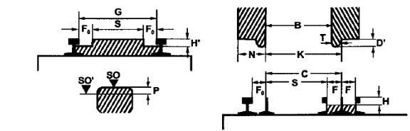
Biggest difference between the two is the allowable gage widening and the check gage. Also the method of measuring the flangeways are different.

NEM Trackwork:
Gmin: 16,5mm MIN
Gmax: 16,8mm MAX
S: 14,1mm MAX
C: 15,2mm MIN
F: (at FROG) = ½ (G-S)
F0: (at Guard) = G-C
H: 1,2mm MIN

NMRA Trackwork
Gmin: 0.649? MIN (16,5mm MIN)
Gmax: 0.672? MAX (17,1mm MAX)
S: 0.564? MAX (14,3mm MAX)
C: 0.605? MIN (15,4mm MIN)
F: (at Frog) 0.050? MAX (1,27mm MAX)
F: (at Guard) Not defined (But is actual G minus actual C)
H: 0.028? MIN (0,71mm MIN)

Note that the allowable flange height for NEM is larger and safe for the 311 deep flange. The NEM 311.1 fine flange will be OK with the NMRA 'H'.

Note NEM flangeways are defined based on the actual G, C, and S employed and the G, C, and S have 'tighter' parameters than under NMRA. Based on a G of mid range (16,65mm), and using 15,3mm for C, and using 14,0mm for S - then the F at the frog would be: 1,3mm - the F at the guard would be 1,4mm. This would be the 'ideal' design NEM criteria. However, that would not be then conforming to the NMRA, in particular - the track check gage would be to small, necessitating resetting wheel sets to to tighter wheel check gage for reliability.

A lot depends on your equipment and the wheel sets you choose to operate.

-ed-


Attachments:
NEM_diagram.jpg
NEM_diagram.jpg [ 16.87 KiB | Viewed 9016 times ]

_________________
-ed mccamey-
COSLAR RR - http://www.coslar.us/
NMRA Standards and Conformance Department
PROTO & FINE Scale Coordinator
I estimate I have about 5 pounds of coupler springs somewhere in the vicinity of my workbench.


Last edited by emccamey on Tue Apr 29, 2008 9:44 am, edited 6 times in total.
Top
 Profile  
 
 Post subject:
PostPosted: Mon Apr 28, 2008 10:23 pm 
Offline

Joined: Mon Apr 28, 2008 10:16 am
Posts: 2
Very informative tho I must admit to being a nivice with track, have tyou a diagram with these labels on them so I can make more sense of these sizes?
Also I will be using mostly Bemo stock which has reasonably small flanges so they shouldnt cause a problem, its just the BtB that I may have to tweak. I assuse it would be possible for Fast Tracks to adjust the numbers to suit in the cnc milling setup to produce a turnout jig to NEM standards? Especially if they can adjust it to suit Tillig track?


Top
 Profile  
 
 Post subject:
PostPosted: Tue Apr 29, 2008 9:39 am 
Offline
User avatar

Joined: Sat Aug 13, 2005 10:48 am
Posts: 365
Location: East Texas - USA
I've added a NEM diagram to the edited posting above. The labels and relationships are the same for NEM and NMRA, only the specifications are different. NMRA does not address the F0 (flange at guard), for the NMRA the flangeway F is for the wing to flange point, and the guard flangeway is derived from the setting of the track check gage C.

You can ignore the SO and SO' railhead part of the diagram, that is a specification on the railhead gaging point location - that is effective only with truly prototypical formed railheads and the differences are so minute, that the effective ranges are unaffected for Gmin and Gmax.

What is critical to any track and wheel standards is the check gages for track (C) and the wheels (K). The check gage is a prime driver of operational performance. The track is a MIN and the wheels is a MAX, otherwise they should be very close together - but not actually the same to avoid interference. There is not a direct compatibility between NEM tack and NMRA wheels and vice versa. Ranges are close and adjustments are necessary to have conformance criteria.

_________________
-ed mccamey-
COSLAR RR - http://www.coslar.us/
NMRA Standards and Conformance Department
PROTO & FINE Scale Coordinator
I estimate I have about 5 pounds of coupler springs somewhere in the vicinity of my workbench.


Top
 Profile  
 
Display posts from previous:  Sort by  
Forum locked This topic is locked, you cannot edit posts or make further replies.  [ 4 posts ] 

All times are UTC - 5 hours [ DST ]


Who is online

Users browsing this forum: No registered users and 1 guest


You cannot post new topics in this forum
You cannot reply to topics in this forum
You cannot edit your posts in this forum
You cannot delete your posts in this forum
You cannot post attachments in this forum

Search for:
cron
Powered by phpBB® Forum Software © phpBB Group